LaserCheck, developed by data M Engineering, measures the actual bend angle during the press brake cycle and returns measurement data to a compatible CNC control. The non-contact system is designed to reduce trial bending, compensate for material springback, and improve angle consistency when sheet thickness, yield strength, grain direction, or tooling conditions vary.
Press brake programs are normally created from nominal material and tooling data. In production, however, small differences in material thickness, tensile strength, rolling direction, surface condition, punch and die wear, and machine deflection can change the final angle. Manual inspection after each bend increases cycle time and still depends on operator judgement.
LaserCheck closes this gap by measuring the part while it is being formed. A compatible CNC can compare the measured value with the programmed target and apply the correction method supported by that machine and controller. Depending on the integration, this may include an additional ram movement during the bend or a corrected value for the next cycle. The objective is not merely to display an angle, but to create a closed-loop bending process that can react to material variation.
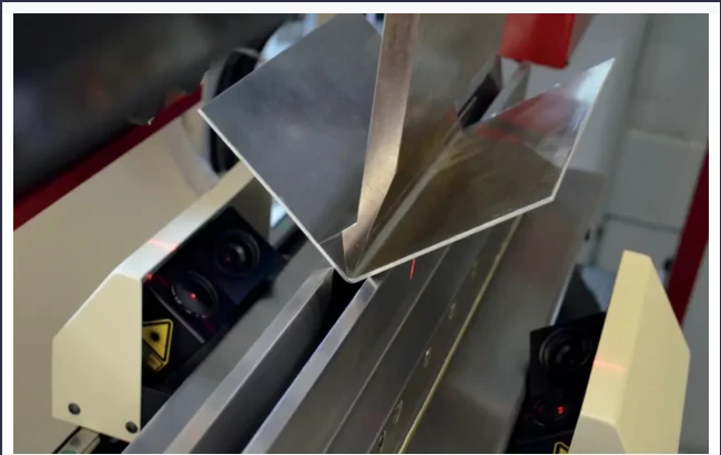
Opposed LaserCheck sensors measuring the workpiece during the bending cycle
LaserCheck uses laser triangulation together with a CMOS or CCD camera. A laser line is projected onto the sheet surface and the camera records the position of the reflected line. Because the geometric relationship between the laser emitter and the camera axis is known, the system calculates the angle between each sensor and the corresponding sheet leg.
Two sensors are installed on opposite sides of the lower tool. The included bend angle is calculated from both measured sheet-leg angles:
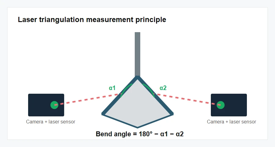
Dual-sensor calculation: bend angle = 180° − α1 − α2
The measurement is contactless, so no probe has to touch the material. Depending on the selected sensor, tool geometry, mounting distance, and controller interface, the system can measure bend angles from 30° to 180°. Opposed sensors also make it possible to compare both sides of the part and support correction across long bending lengths.
Springback occurs when the sheet relaxes after forming pressure is reduced. LaserCheck can monitor the angle during controlled decompression. Optional strain-gauge measurement can be used to evaluate the force change at the machine frame and help the control determine when the material has entered the springback phase. The calculated correction is then applied to the following ram movement or production cycle.
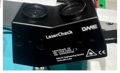
LaserCheck sensor module combining laser projection and camera-based measurement
The model must be selected according to lower-die width, lower-tool height, required working distance, machine length, accuracy target, and CNC interface. The table below uses the current technical data published by data M Engineering for the Portable, 10L, 11, and 12 configurations.
V6–V60
55–85 or 85–110 mm
90–220 mm
30°–180°
TCP/IP or Modbus
LaserCheck 10L
V6–V60
55–85 or 85–110 mm
30°–180°
Better than ±0.2°
USB, up to 5 m
LaserCheck 11
55–85 or 85–110 mm
90–220 mm
30°–180°
Better than ±0.1°
LaserCheck 12
V6–V100
55–85 or 85–110 mm
165–380 mm
Better than ±0.1°
GigE, up to 50 m
Selection note: The supplied Chinese reference also lists earlier or project-specific LaserCheck 10, X, and XR configurations. Their availability and specifications should be confirmed separately. Final accuracy, frame rate, die range, working distance, and controller compatibility must be checked for the actual press brake, tooling, and interface before ordering.
LaserCheck communicates with the press brake control so that measured angles can be converted into automatic correction values. Typical communication methods include TCP/IP, Modbus, RS232, and EtherCAT. Supported implementations may include Delem, ESA, Cybelec, Amada, Bystronic, Robosoft, Step Automation, and other controls that provide the required software option and open communication interface.
For integrated operation, the CNC must be able to receive the measured angle, compare it with the programmed target, and command the correction function supported by the machine. Controller model, software version, available communication ports, machine safety logic, and PLC access must therefore be checked before retrofit work begins.
Current CNC machine configurations can be reviewed on the CNC press brake machine page. Existing machines may require an interface assessment through the available press brake upgrade solutions.
LaserCheck can be supplied as a fixed sensor system or as a portable retrofit package. Optional components expand the measurement range, support springback detection, and allow the sensor pair to move between different measuring positions.
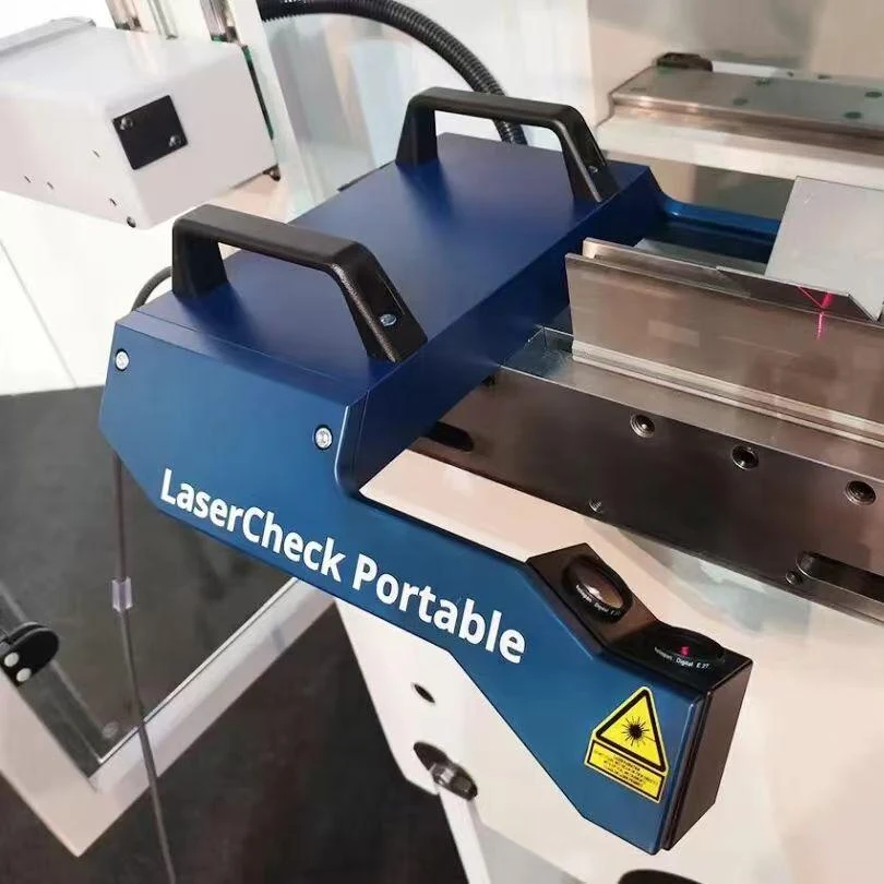
LaserCheck Portable combines the measuring components in a mobile unit for compatible press brakes with die widths from V6 to V60. It is intended for machines up to approximately 3 m wide using supported Delem, ESA, or Cybelec controls. Magnetic mounting and a pre-calibrated, fully wired configuration can simplify retrofit installation without requiring changes to the punch or die.
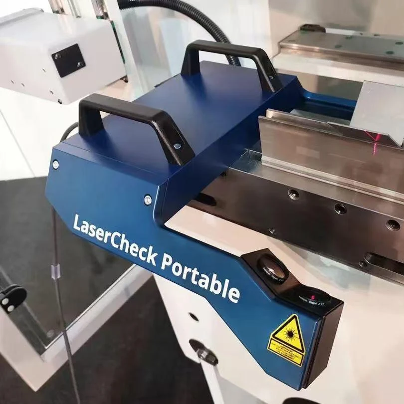
LaserCheck Portable mounted at the press brake tooling area
Correct system selection requires the press brake model, controller and software version, lower-tool dimensions, machine length, intended measuring positions, workpiece geometry, and required correction strategy. These data should be reviewed together before the sensor model and mounting arrangement are finalized.