These sheet metal bending guidelines explain the minimum flange lengths, hole-to-bend clearances, bend reliefs, Z-bend limits, inside radii, acute bends, hems, and tooling restrictions that should be checked before press brake production. Use the tables as practical design references and confirm final values against the selected material, sheet thickness, tooling, and machine capacity.
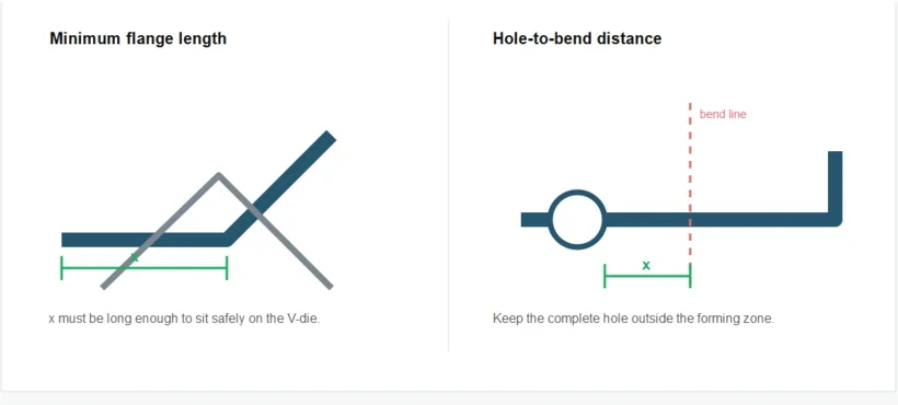
Tooling imposes minimum dimensional limits that must be considered to ensure that a bent part can be manufactured. If a flange is too short for the required lower die, the specified bend cannot be produced. Actual limits may vary depending on the part geometry and bend length.
For an initial estimate of the required bending force and V-die opening, use the press brake bending calculator.
Minimum flange length: correct and incorrect design
5 mm
8 mm
0.8 mm
5 mm
1 mm
5.5 mm
10 mm
1.5 mm
10.5 mm
2 mm
9.5 mm
13 mm
12 mm
15.5 mm
3 mm
14 mm
4 mm
18.5 mm
23 mm
5 mm
24 mm
30 mm
6 mm
30 mm
38 mm
8 mm
38 mm
45 mm
10 mm
45 mm
59 mm
12 mm
59 mm
88 mm
15 mm
88 mm
5 mm
8 mm
0.8 mm
5 mm
1 mm
5.5 mm
10 mm
1.5 mm
10.5 mm
2 mm
9.5 mm
13 mm
12 mm
15.5 mm
3 mm
15.5 mm
4 mm
22.5 mm
27 mm
5 mm
30 mm
38 mm
6 mm
38 mm
43 mm
8 mm
43 mm
57 mm
10 mm
57 mm
72 mm
12 mm
72 mm
88 mm
15 mm
104 mm
88 mm
Holes or cut-outs positioned too close to a bend line may distort during forming. A sufficient clearance must therefore be maintained.
The minimum distance to the bend is the same as the minimum flange length specified above. In the minimum-flange diagram, dimension x represents the distance from the bend line to the nearest edge of the contour.
If holes or contours must remain close to the bend for functional reasons, bend reliefs can be incorporated into the design as described in the following section. Distortion caused by an insufficient design clearance cannot be controlled reliably.
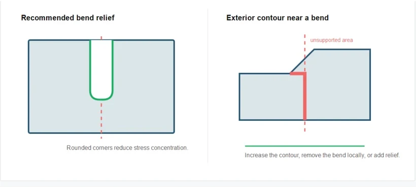
If the minimum hole-to-bend distance cannot be maintained, bend reliefs can be added to prevent holes or cut-outs near the forming zone from distorting. The following points should be considered when designing bend reliefs:
Design example: bend relief
If a part contains tapered flanges or other external contours close to the bend line, the same rules used for minimum flange length apply.
Where the external contour reduces the available flange below the minimum length, the material is no longer fully supported by the lower die. This area may distort during bending or may not be formed completely.
There are three ways to prevent this condition:
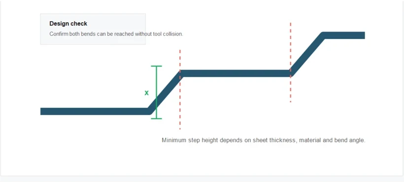
For two consecutive bends forming a Z-profile, the tooling requires the following minimum step heights.
Z-bend example
11.5 mm
18.5 mm
1.5 mm
12.5 mm
2 mm
15 mm
20.5 mm
2.5 mm
26 mm
3 mm
24.5 mm
35 mm
30 mm
35.5 mm
5 mm
36 mm
6 mm
46 mm
58 mm
8 mm
59 mm
72 mm
10 mm
70 mm
86 mm
12 mm
98 mm
57 mm
15 mm
128 mm
72 mm
11.5 mm
19 mm
1.5 mm
13.5 mm
2 mm
18 mm
26.5 mm
2.5 mm
32.5 mm
3 mm
26 mm
36 mm
36 mm
53 mm
5 mm
43.5 mm
6 mm
53.5 mm
63.5 mm
8 mm
65.5 mm
78 mm
10 mm
92 mm
86 mm
12 mm
109 mm
57 mm
15 mm
181 mm
72 mm
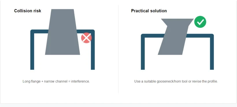
If the flanges are too long or the designed U-profile is too narrow, the workpiece may collide with the upper tool or upper beam. The achievable dimensions for U-profiles depend on the available tool and beam clearances.
For material thicknesses of 6 mm and above, part size and geometry may require a straight punch instead of a gooseneck punch.
Available working lengths, control configurations, and tooling options can be reviewed on the CNC press brake machine page.
Example: tool collision with a U-profile
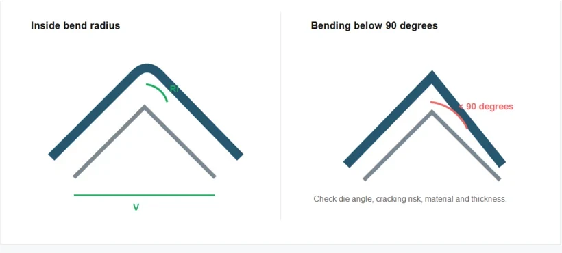
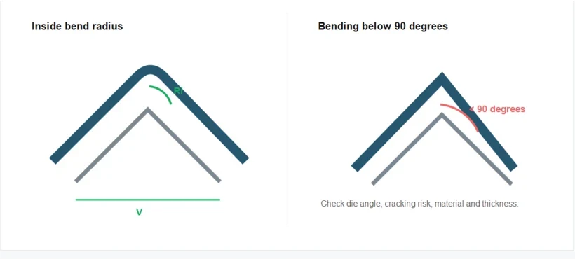
Inside bend radius dimensions
0.5-1
4-8
Approx. 0.5-1.7
0.8
4-12
Approx. 0.8-2.5
1
1
Approx. 1.0-2.5
1.5
1
6-16
2
1-2
10-20
Approx. 2.0-4.2
1-2.5
12-24
Approx. 2.5-5.0
3
1-3
16-30
Approx. 3.0-6.3
4
1-4
20-40
Approx. 4.0-8.0
5
1-5
30-50
Approx. 5.0-10.1
6
1-6
30-60
Approx. 6.0-11.8
8
4-8
50-90
Approx. 10.2-18.1
10
4-10
70-120
Approx. 14.0-24.2
12
5-10
80-120
Approx. 15.8-24.4
15
6-10
90-120
Approx. 17.9-24.1
0.5-1
4-8
Approx. 0.5-1.8
0.8
4-12
Approx. 0.8-2.6
1
1
Approx. 1.0-2.7
1.5
1
6-16
2
1-2
10-20
Approx. 2.0-4.6
1-2.5
12-24
Approx. 2.5-5.7
3
1-3
16-30
Approx. 3.0-7.0
4
1-4
20-40
Approx. 4.0-9.0
5
1-5
30-50
Approx. 7.3-11.2
6
1-6
30-60
Approx. 7.2-13.6
8
4-8
50-90
Approx. 12.2-19.9
10
4-10
70-120
Approx. 16.1-26.6
12
4-10
80-120
Approx. 18.5-27.3
15
4-10
90-120
Approx. 21.0-27.8
0.5-1
4-8
Approx. 1.3-2.1
0.8
4-12
Approx. 1.2-3.0
1
1
Approx. 1.6-3.0
1.5
1
6-16
2
1-2
10-20
Approx. 2.6-5.0
1-2.5
12-24
Approx. 2.8-5.9
3
1-3
16-30
Approx. 3.8-7.5
4
1-4
20-40
Approx. 4.6-19.6
5
1-5
30-50
Approx. 6.9-12.0
6
1-6
30-60
Approx. 6.9-14.1
8
4-8
50-90
Approx. 12.0-21.6
10
4-10
70-120
Approx. 16.1-29.6
12
5-10
80-120
Approx. 21.9-29.1
15
6-10
90-120
Approx. 20.4-28.5
The following processing requirements apply to sheet metal bends with an included angle below 90°:
–
–
–
30-35°
Up to 2.0 mm
–
35-40°
Up to 4.0 mm
Up to 2.0 mm
40-45°
Up to 6.0 mm
Up to 6.0 mm
45-60°
Up to 8.0 mm
Up to 8.0 mm
Up to 2.5 mm
No specified limit
No specified limit
Up to 5.0 mm
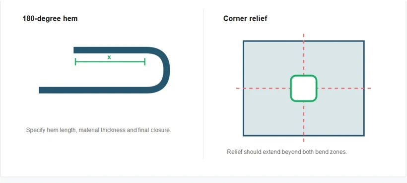
The following requirements apply to 180° hems:
Hem design example
0.5 mm
10 mm
0.8 mm
10 mm
10 mm
1.5 mm
10.5 mm
2 mm
Laser-cut features have a minimum achievable width and must be represented correctly in the CAD file. Cut lines at the end of a bend should be designed as bend reliefs. A small cut-out can be added to the drawing, or a corner-relief option can be specified. Without sufficient separation between adjacent bend zones, the material may continue tearing along the cut.
Reliefs next to a bend must have a minimum width and depth equal to the material thickness. Sufficient clearance must be maintained around the bend to permit accurate forming while preserving part stability.
Corner reliefs must extend at least 1 mm beyond the bend zone in each direction. This additional length provides sufficient forming clearance and may need to be increased for thicker material.
A minimum clearance of 0.2 mm must be provided between two overlapping tabs to ensure correct calculation and reliable manufacturing.
If existing equipment cannot meet the required tooling clearance, bending accuracy, or automation level, review the available press brake upgrade solutions before changing the component design.